|
|
| Home |
Monitor/Keyboard/CNC Controller Arm
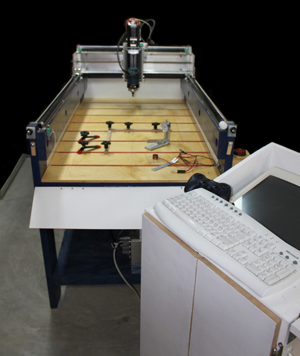
Fig. A Above shows the CNC table as I originally made it, including the standalone computer console on the right that held an old CRT monitor, which I had laying around. I felt good about being able to re-use the monitor, and now you can't even give them away to goodwill places! However, floor space is pretty scarce in my shop, so when I had a chance to buy a nice flat screen monitor at a garage sale for $20, I jumped at the chance to free up the room the old console was taking. So, how to mount it? It was always an option to put the computer case under the table, but placing the monitor and keyboard was problematic. Added to this was my desire to call out more explicit controls for the table than just the keyboard. This page is a build log about the solution I came up with.
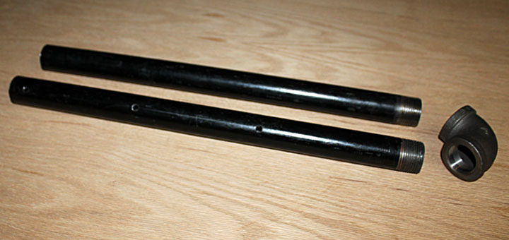
Fig. B I started with a 36 inch length of 1 inch ID black pipe, threaded on both ends, and cut it in half. I thought about using larger diameter PVC, but it was just a few bucks more for some smaller but even more rigid pipe. If you want your monitor to be placed higher than mine, you might consider a longer piece of pipe. On one of the pieces, I drilled three 1/4 inch through holes, making sure they were all centered and upright. I also got a 1 inch 90 degree elbow.
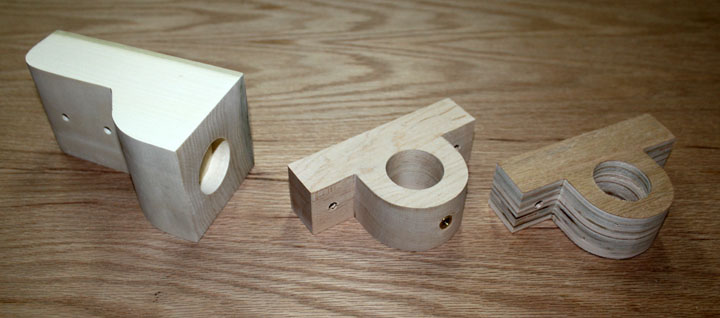
Fig. C Here are the attachment brackets to fix the pipe to the table, cut with a band saw from some glued up leftover birch plywood and hard maple. The left one is the bottom bracket, which has a nylon washer in the bottom of the pocket hole to reduce wear. The middle one has a brass threaded insert that allows a knob to lock the position of the arm. Toward that end, detents were drilled into the pipe at the fully closed position (arm swung out of the way) and at two normal use positions, although the arm can be positioned anywhere along its arc. The one on the right is the top bracket that is closest to the elbow.
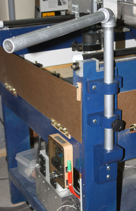
Fig. D Here the arm is mounted on the table where the E-Stop switch used to be. The brackets in Figure C have been painted to match the table and lag screwed into the table leg. The knob was inserted into the middle fixture and the arm locked into position. Also, the pipe was painted with a hammered silver finish and epoxy added to the threads of the elbow. So far, so good!
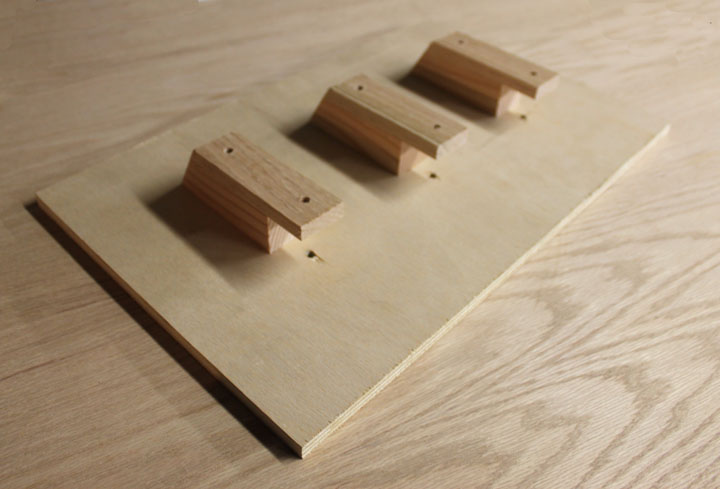
Fig. E I then cut a piece of 1/2 inch plywood to 19 by 12 inches - adjust this dimension to accommodate the size of your keyboard. I also cut three pieces of wood the exact height of the outside diameter of the pipe (which was 1.30 inches) and also cut three longer pieces of hardwood. These I glued together as shown above, displayed upside down, and match drilled them out to accommodate the pipe. This shelf will be bolted to the iron pipe to form a stout base for the keyboard and monitor.
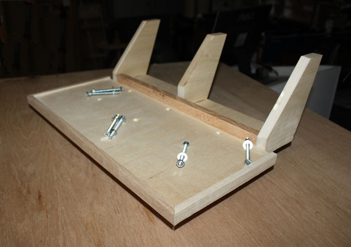
Fig. F I decided I also wanted a more convenient and obvious controller for the CNC table to be built into the arm, so placing the panel behind the keyboard made the most sense. Here is the shelf in Figure E turned right side up with two side panels and a middle support glued and screwed onto the shelf. A rabbet is cut along the inside front edge of each side panel to fit a 17 x 6 aluminum control panel that will support the switches. The middle support not only braces the center of the panel, but provides the primary support for the monitor bracket to screw into. A trim strip along the bottom of the panel helps to enclose it, and I've added some edge trim to keep the keyboard in place as well as hide the plywood end grain. Some folks do not like the looks of wood on their CNC machines and prefer a more mechanical look. You could certainly do this project in sheet metal if you prefer. I like the warm look and feel of wood, and I had everything on hand.
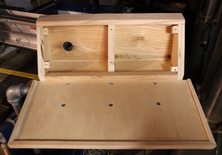
Fig. G Here the shelf is mounted on the pipe arm, and a top and back have been added to the panel box, along with wood "tabs" glued to the sides make placement of the panel mount screws easier.
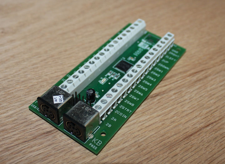
Fig. H The magic that makes the control panel work is the keyboard emulator shown above. I thought about programming an Arduino to do this, but if you've ever programmed keystrokes into a PC before, you soon discovered that it was trickier than it first looked. Toward that end, I decided to use an I-PAC2 device to handle this, shown above. At $39, it is just about the cost of an Arduino anyway, but still it's the most expensive component of this project, including the keyboard or monitor! It will save me a lot of time from experimenting, though. The IPAC was developed for builders of MAME type game systems. The regular keyboard plugs into this device, and the other connector goes into the computer's keyboard input. All keystrokes from the regular keyboard are just passed through as normal, but a push button switch wired to one of the 32 inputs to the board will generate whatever keystroke(s) I tell it to send to the computer, and the I-PAC takes care of multi-key, timing, debounce, and rapid repeat issues. The I-PAC also comes with a free utility to program it with the keystrokes that are generated by each switch closure. Although this board uses PS/2 connectors, the other end of the cable can be a USB if you order it so. All the I-PAC does is create keystrokes for you - if you can do everything you need to do with Mach 3 through the keyboard, then this approach will work just as well to create an explicit control panel. If you need very fine movement control at high speed, then the keystroke approach may not work for you - a more robust MPG (Manual Pulse Generator) might be the way to go, but they are typically much more expensive.
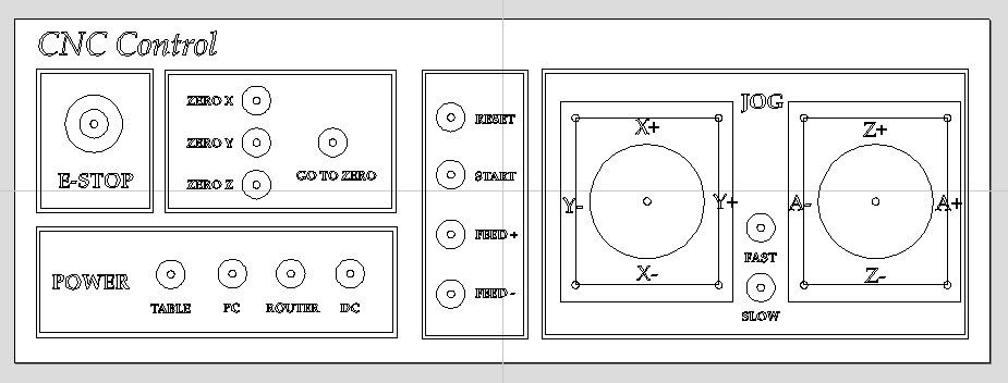
Fig. I I made a list of commands I use most often to help design the panel, concentrating on those that are used while the table is in operation. While the table is being set up, I don't mind searching for the right command and keystroke combination on the keyboard, but once cutting has begun, I would like a simple button right in my face to do those operations. The way you use your table might be different, so you might choose a different set of controls to fill out the panel, but the principle is the same - that's what having a custom control panel is all about. Figure I is what I come up with using Aspire as the layout tool. On Page 3 of my CNC build, Figure 22, I showed how I previously mounted a large lighted switch for the E-Stop. I got used to a lighted E-Stop switch since it reminds me the machine has been left on. Also, since I am right handed the trackball needs to go on the right of the keyboard, which meant I needed to mount the arm where the E-Stop was before, so I will incorporate the E-Stop switch into this panel, although it's signal will not go through the IPAC, but will go directly into the G540, wired just as before. The two large blocks on the right are for joysticks to move the gantry around the table. From this, I made up a spreadsheet that lists each switch, each IPAC input, and each Mach 3 hotkey needed to cause the correct function to occur, and used this both as a wiring guide as well as a programming reference while using the utility to program the IPAC. The design of Figure I allowed me to generate a toolpath to cut all of the holes for the switches and joysticks in the aluminum panel, as well as export a graphics design to print clear labels for the panel.
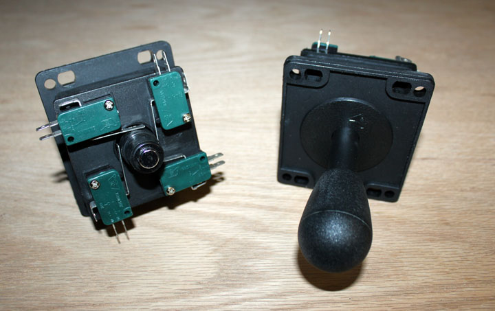
Fig. J These are the joysticks I used - they are arcade game joysticks, chosen primarily for how sturdy they are made - arcade controls are certainly made to withstand a beating. Search for "competition arcade 8 way joystick" and you will find many vendors and colors, etc. They are not expensive - mine were $8.95 apiece. These work simply by the stick movement causing one or two of the micro switches to be pressed at a time, so each stick takes up four inputs to the I-PAC. (Note - this joystick is not the type that have potentiometers that provide an analog position signal. This kind simply substitutes micro switch closure for pressing the arrow keys on the keyboard.) They are called "8 way" joysticks because they allow diagonal movement to trigger two switches at the same time, resulting in 8 different switch states.
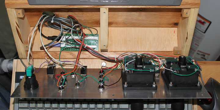
Fig. L Here is the wired back of the panel. The wiring is simple - each switch common goes to ground, and the Normally Open lead from each switch goes to the appropriate screw terminal on the IPAC. +12 volts comes from the table to power the lighted EStop and the relay switches.
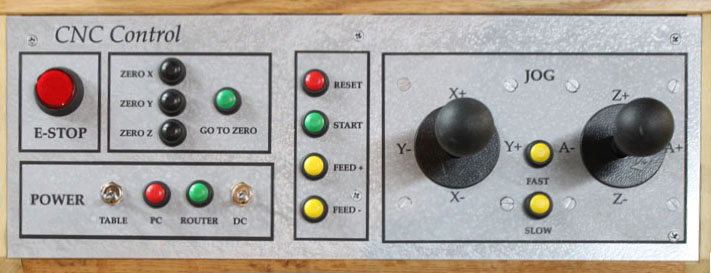
Fig. K Here is how the front panel turned out. After the holes were cut by the CNC, the panel was sprayed with some hammered silver, and the labels printed and applied. (The hammered silver looked great on the pipe, so I thought I would match the panel with it, but the labels do not work well on the orange-peel effect of that paint, so were I to do this over, I would not use a hammered finish. As it is, it looks ok, though. Here's a panel I did for a project using the same technique that looks much better.) The E-Stop, wired exactly as before (normally closed), is on the upper left. As for color coding the switches, I used green to indicate an operation that would result in immediate movement of the router, thereby advising caution. Yellow indicates a change in that movement, and red indicates a command with immediate and significant effects, like E-Stop, Reset, and reboot the PC, but not having a color code is probably just as well. Below the E-Stop is a toggle switch to power a relay to turn on the main 48v power supply to the table steppers and the G540, a PC push button wired in parallel with the power button on the front of my PC case to boot the PC, the green router button issues the "spindle turn" command to Mach, and a toggle switch powers another relay to turn on the dust collector. Above those are black push buttons to zero the X, Y, and Z axes, and a Goto Zero command button. In the middle are buttons to issue the Reset, Cycle Start, Increase Feed rate, and Decrease Feed rate keystrokes. On the right are the joysticks with a "fast" button to increment jog speed, and a "slow" button to decrement jog speed in between. You can select whatever commands you like and group them in any way that makes the most sense to you. If you need more space on the panel for swtiches and don't anticipate a 4th axis, you could substitute a Momentary-Off-Momentary type toggle switch for the Z axis motion and forget the whole right hand joystick.
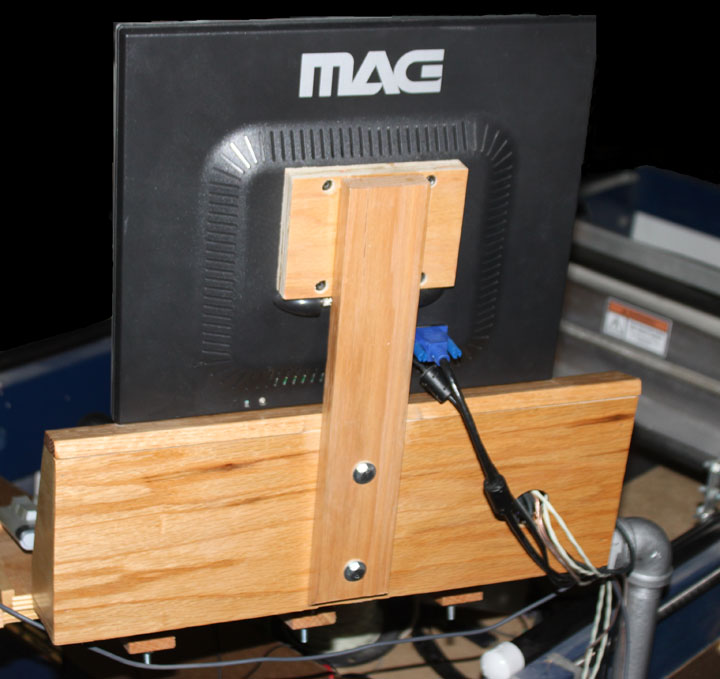
Fig. N Here is the monitor mount screwed in place with holes drilled to accommodate bolt hole pattern in the back of the monitor. A replacement monitor might need a different top piece to accomodate a different bolt pattern, so I made this support removeable.
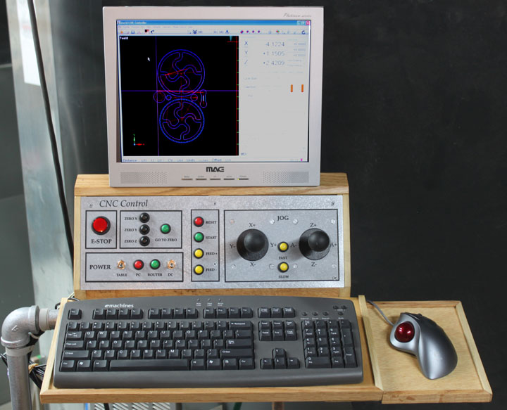
Fig. O Here monitor arm is complete - I've added a side shelf for the trackball, and the whole thing given a few coats of satin poly finish. You could make the shelf larger for a mouse pad, but due to some wrist issues, I prefer a trackball anyway. I am using a version of Gerry Grzadzinski's 2010 screen set for Mach that has been modified to use standard Mach keystroke assignments. I am pretty happy with how it all turned out, and now I have some shop floor space freed up. I got used to using those buttons very quickly.
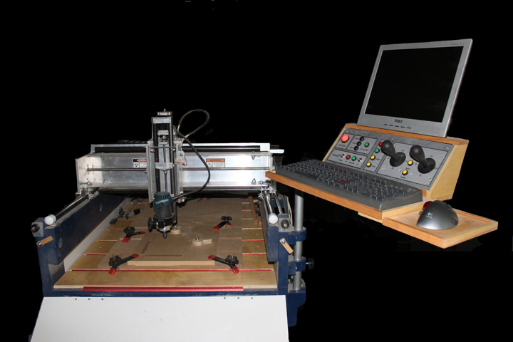
Fig. P Here is the whiole thing, ready to make some dust! Several have suggested that this approach is not good because of how much the arm potentially rocks back and forth during operations. I believe others have seen the problem, but I have to say that is not a problem here. Perhaps because the whole thing is made from lumber that there is more motion damping, or perhaps it is because my machine doesn't typically move as rapidly as others have built theirs. My machine moves its fastest while jogging, and I have no trouble doing so with the joysticks. The arm moves very little during cutting operations and I have no problem using the screen, keyboard, or mouse at that time. |