|
|
|
| Home |
Page 5 ADD-ONS
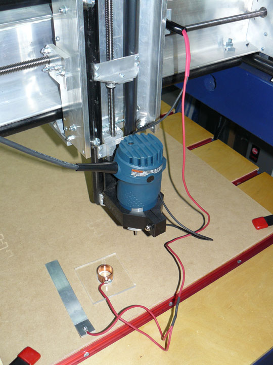
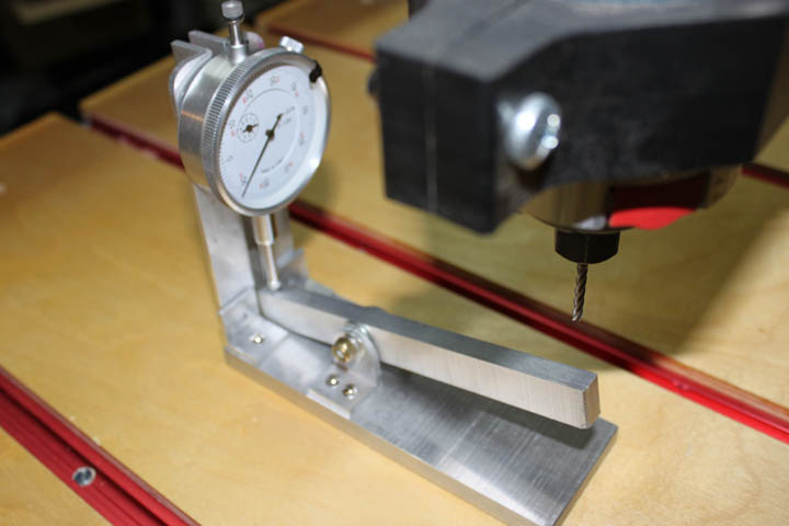
Fig. 35 Above shows the zeroing probe set, the design of which includes the device and some mods to Mach3 I got off the net from a person called "erniebro" - Thanks, Ernie! The way it works is when you have the origin located on the material to be routed (X=0, Y=0), you clamp the material onto the table, and place the plastic device with the copper pipe close to that location. At the bottom of the copper pipe is a crosshair, scribed onto the Plexiglas, that allows you to locate that point with good precision. Once in place, you jog the router bit over this pipe, and lower it part way into the pipe. You then click on a button on the Mach screen, which causes the bit to move forward and back, electrically touching the pipe on both sides, and then Mach knows where halfway is, and then it moves the bit right and left, until touching and then it knows exactly where the center of the pipe is. It then positions the bit above the pipe, right over X=0 and Y=0. You then remove the plastic piece and place the aluminum strip to cover the origin point. Clicking on another screen button causes the bit to lower until it touches the aluminum strip, at which point it knows exactly where the surface of the material starts (Z=0) plus the thickness of the aluminum strip (.125 inch). It then raises the bit half an inch, and Voila! - your machine has aligned its X,Y, and Z axis with the origin of the material, regardless of where it was clamped to the table. Unfortunately, the Bosch Colt is double-insulated, which means the bit or collet does not make electrical contact with the table frame, so a large alligator type clip on the collet is needed to complete the circuit. (This was solved later on.) The hold-down clamps you see in the movie and on the edges of Fig. 35 are some I got at HF on sale for cheap, and they work great.
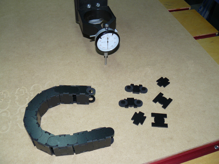
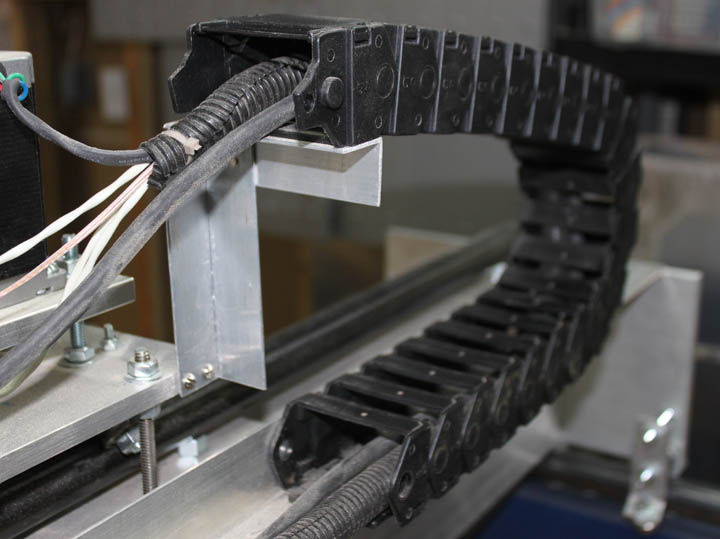
Fig. 36 Above is the dial indicator attached to the router mount. This allowed me to measure table tilt relative to the X and Y axes. Lengthwise there is a 100 thousandths difference from one end to the other, and about 40 thousandths across. Not too bad for the lack of precision instruments used when I built the table bed. At this point, I have two choices - by placing some layered shims under the plywood base, I can even up the table, or I can just put a sacrifice board on the table and run an end mill across the whole surface at a constant depth, making it flat with respect to the router bit. I think I will even up the base with shims, making it easy to replace the sacrifice board when needed. Also in Figure 36 shows some of the pieces that were cut out in Fig. 32, as well as how they snap together to form the cable chain on the left. This should keep my cables out of the way while the router is working. They were a close fit and snapped together quite well. Unfortunately, I found that when they had cable in them and were flexing due to its normal movement, the parts needed to be glued, which I did. This had the effect of making it very difficult to add or take out any wiring that I would want to add later. I therefore went looking and found a length of "Zipper" style IGUS cable they make for this purpose on Ebay for $24, which was a bargain and had enough to supply both X and Y axes. This chain allows the top pieces to pull away and makes it quite easy to add or take out wires. A picture of how its mounted is shown in Figure 37.
Fig. 37
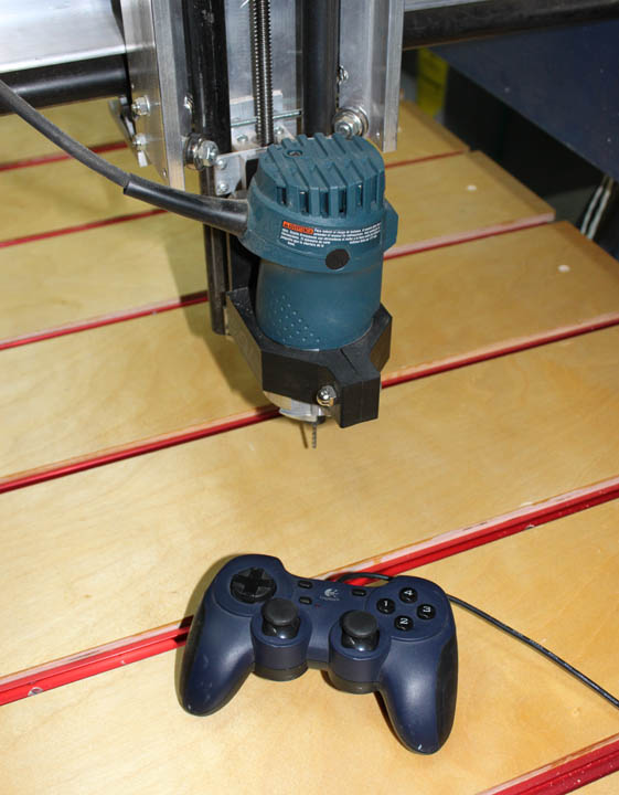
Fig. 38 Above is a useful and cheap add-on. You may often want to be looking closely at the bit while you position it, which is awkward with the keyboard. Here, a game controller is used as a pendant, which allows you to get close while positioning and keep your keyboard away from the dust. (A plastic keyboard cover might be a good idea, but I haven't gotten one yet - they make one for just about any keyboard design.) If you browse goodwill stores or look on Craigslist, etc. you can often find this kind of game controller for next to nothing - brand new they are $20. Most of these work by plugging in to a USB - make sure you get the software with it or can download it from the manufacturer. This software translates the movement of the game controller switches to keystrokes you can assign with the software. So, if Mach 3 wants the page up and page down keys to move the Z axis, you just assign those keys to two of the buttons on the game controller, and then do the same for the X and Y axis. With use, however, I was always getting confused with the buttons, and the ways I tried to label them weren't very good. Since there is no feedback on the device itself, you have to be looking at the Mach screen anyway, so you might as well be using the keyboard.
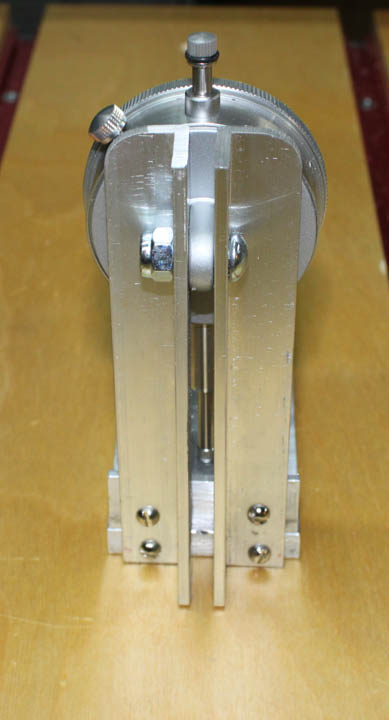
Fig. 39 In Figure 35, the device to zero the Z axis relies on an alligator clip onto the router collet, and a 1/8 inch strip of aluminum. One time I was using this, the router bit didn't stop when it made contact, but kept bearing down. Luckily, I was right next to the Estop switch, but it ruined the tip on a V bit before I could hit it. I chalked it up to my own carelessness, and was careful from then on. However, when it happened a second time, and ruined another bit, I was not a happy camper. Initially I thought that it was due to a bad connection at the collet, but I have since learned that others have seen the problem, so I have reported it. (Note from later: I've since learned that the software mods (mentioned at the top of this page) for the probe has a bug in it that allows for the occasional hangup. I've since repaired the bugs.) The winter 2009 issue of Digital Machinist magazine had an interesting answer to the problem. The one I built shown above is a bit different than the all-steel one shown in the magazine - it is made from aluminum scraps left over from building the gantry, but it seems to work just fine. This is practical due to the availability of accurate $10 dial indicators from Harbor Freight. The way this works is that you lower the router bit until the dial indicator reaches zero. This occurs when the rocker bar is parallel. Then, just like before, Mach 3 has the offset height of the device specified and now knows where the surface is and sets that to zero. To calibrate it after it's built, the rocker bar had a piece of 1/2 inch material placed under both sides of the pivot, ensuring the bar was parallel, and the dial face was then set to zero. Then, a milling bit is lowered at the far end of the bar until the indicator read zero. The bit was then immediately moved to cut a block of material. The height of the resulting cut was measured with a caliper and recorded and specified to Mach 3's offset. From then on, I just lower the bit until the dial reads zero, and click - it's done. Although one can attempt to make this height be equal to some round number, like 1.000 inch to so, there really isn't any need as long as you accurately know what the true height is when the pivot arm is parallel. Below is the back of the gauge.
Fig. 40 I've since gone on to another zeroing method, but the above project was fun to make and I've used it for several purposes other than tool zeroing on the CNC table. On CNCZone I learned about the virtues of having home switches. The provide a way for Mach3 to know where the router bit is on the physical table space, independent of where it is relative to the material being cut. Running a table without them is called running "unreferenced" and allows the machine to go off its limits. To prevent this I installed limit switches at the end of travel on each axis. A better way than using limit switches is to install home switches, which can be placed anywhere on the axes, but are always at a fixed location. When you power up the machine, you run a routine that seeks these home switch positions, and from then on Mach knows what the limits of travel are, as well as defined areas for tool changes, zeroing locations, etc. Just like limit switches, the mechanical roller microswitches can be used, and are fairly repeatable, but magnetic ones are better, so I made some as described on a thread by Roman Black. (Thanks, Roman!)
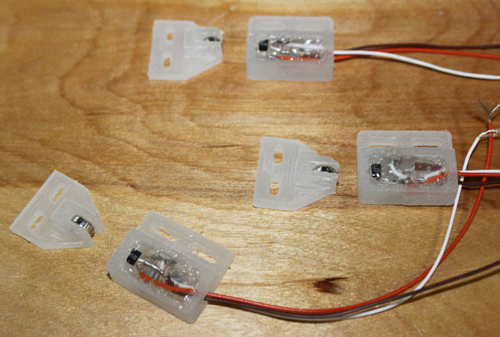
Fig. 41 Above are shown the home made magnetic switches. The white plastic parts I laid out in Vcarve and cut out of cutting board material. The smaller ones on the left have small rare earth magnets glued in them, 10 for $3 at Harbor Freight. The right hand pieces have a Hall effect sensors (it turns on in the presence of a magnetic field) along with an LED and two resistors, potted with some E6000. The three wires have +5 and ground, and the signal that goes into the G540 input. Nice having no moving parts for this. From day one, the biggest single problem I had using my table was the noise it generates. Most of the noise from a router is the noise generated by the fan inside it, not from cutting anything - the difference in sound level from cutting to not cutting material is hardly noticeable. I measured a whopping 105 dB from my table with the 33,000 RPM router and my shop vac running. Couple that with a one to two hour carving and the fact I have a basement workshop means that I usually have to wait until others in the house leave before I can do much work while wearing shooter's hearing protectors. I went to the 2010 CNC Workshop and saw a spindle system for the first time (water cooled using a VFD for control) and just couldn't believe how quiet they were. Unfortunately they were $300 or more for the spindle, and $150 or more for the required VFD that needs 220 volts, so I balked. Then I heard about Roman Black's new device called the SuperPID. The SuperPID is a speed controller for routers, but not like many other speed controllers. Your typical built-in or add-on router speed controller simply cuts the power to the router to get to a slower speed setting. Unfortunately, when it slows the reduced power also reduces its ability to cut. A PID controller is one that uses feedback from the thing being controlled to maintain a set level of performance. (PID stands for Proportional Integrative Derivative, which describes the formula used to adjust the variables to maintain performance.) In this case the performance to maintain is speed, so a tachometer for the router bit is needed to supply the feedback loop. This allows you to set the speed at which you want to cut, and then the SuperPID will continously adjust power to the router in order to maintain the desired speed, even while cutting. This would allow me to go from a very loud 33,000 rpm router to a *much* quieter 7,000 or 10,000 rpm, and not bog down when it digs into a piece. It will also make cutting plastics and aluminum much nicer because it avoids melting. Roman offers the SuperPID as a kind of kit - it involves making a case, adding a power supply, and modifying the router. If there are any speed controls or soft-start features on the router, they need to be bypassed. Also, some kind of mount for an infrared sensor has to be made in a place where the turning shaft of the router can be painted black and white to generate the reflective feedback signal. All that's a bit of work, but its worth it.
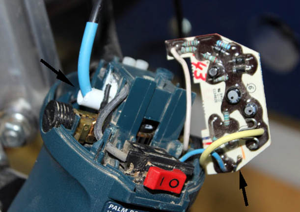
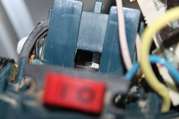
Fig. 42 Above shows the mods needed on my Bosch Colt router. The left arrow points to where I glued a tube on the side of the bearing housing and epoxied it in place. Then, the sensor was inserted into the tube such that the end was about 2mm from the spindle shaft. The arrow on the right points to a solder jumper necessary to defeat the action of the TriAC which was in place to provide a "slow start" feature on the router. The SuperPID will now provide this action.
Fig. 43 Also necessary was to paint one half of the spindle shaft white, and the other black. You can see this inside the square hole in the housing above. In this way, a transition from black to white and then to black happens once per revolution, providing the feedback the SuperPID needs to control the router.
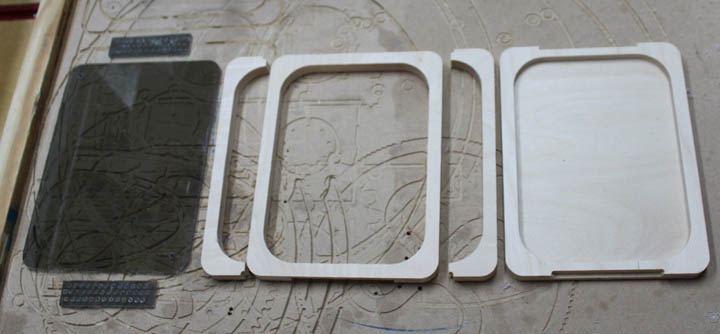
Fig. 44 Next I needed a box to house the SuperPID. I designed a box for the device using .5 inch Baltic birch plywood pieces and some smoked Lexan for a cover. Since there is a heat sink on the SuperPID, I added vents at the top and bottom of the box. Figure 44 shows the pieces from the CNC table.
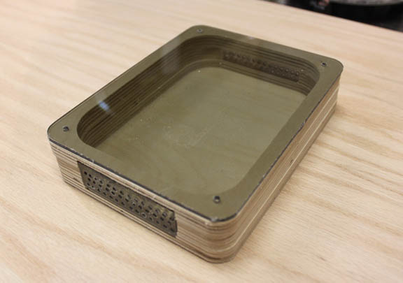
Fig. 45 Here's the pieces in Figure 44 glued up into a box for the SuperPID. A little sanding and some polyurethane will make it ready for action.
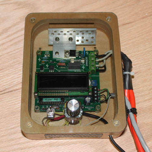
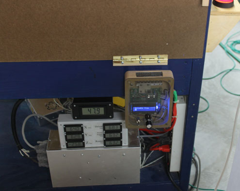
Fig. 46 The completed box - the SuperPID is mounted and wired. An additional heat sink of 1/8 inch thick aluminum angle that matches the box's vent has been added, and the switch to left of the knob switches speed control between the knob in the center, and Mach3's speed control from the computer screen. One of the two orange wires on the right goes to an AC plug, and the other goes to the router plug. The upper part of the PC board handles controlling the AC power and is opto-isolated from the bottom part that talks to the computer and implements the PID control. The chip is version 1.5. The switch on the bottom left controls the speed input of the router by selecting either the knob setting on the right, or by selecting Mach3 control of the speed. The advantage of the latter is that I can specify cutting speeds in my CAM software when I select a particular tool, and it will be included in the Gcode, and the speed set automatically.
Fig. 47 Above is the SuperPID controller installed on the table - fired up and ready to go. It made a huge difference on the noise level while cutting. Normal conversations are now possible while cutting, and the lower speeds allow cutting plastics and aluminum without worrying about anything melting.
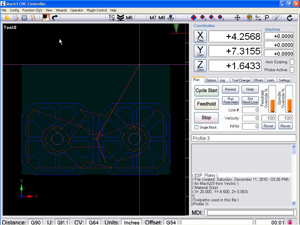
Fig. 48 Another very nice enhancement is Gerry Grzadzinski's 2010 Screen Set, a new user interface for Mach3. It has several enhancements for auto tool zeroing (which assumes the table is in reference mode but still works with the probe type zero device at the very top of this page) and just makes Mach3 look much more like a regular Windows program. As you can see, the toolpath display is much larger while still having critical controls on a tabbed interface on the right. For $20, it made my CNC seem like a whole new machine! Well recommended. Hope you found some of the info on this site useful. Stay tuned for more enhancements as they happen. Thanks for viewing! |