|
|
|||||||||
| Home |
Page 4
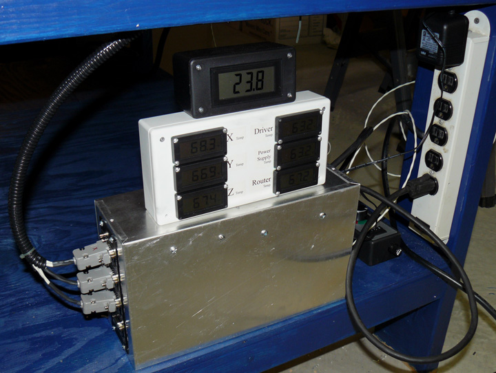
Fig. 26 Above is the power supply unit. The aluminum box contains a fan, barrier strip for the power connections, the switcher power supply shown on Page 1, a relay to control the power to the router, and the Gecko unit you can see mounted on the left side of the box. The light colored box above it contains a small circuit board that takes in +12V and converts it to +5V (using a 7805 regulator) to drive the voltmeter in the black box on top, and +1.5V (using an LM317 regulator) to drive the six temperature meters. On the left are the stepper power cables plugged into the Gecko 540 with a 2.7K resistor in each hood. On the right is a power strip that the aluminum box plugs into, as well as a wall wart that feeds +12 to the temperature box and the bulb in the lighted e-stop switch. Coming out of the power box on the lower right unseen is a power cord that is switched through a Crydom relay connected to the Gecko. This power cord is plugged into a HF speed controller for the router, which you can just see at the lower right of the box, giving me at least a little control over spindle speed. Although there are only "slow, medium, and fast" settings, it is a much more expensive problem to have an accurate idea of the RPMs for the cutting edge, so I'll settle for that for now. In the photo above, the voltmeter shows 23.8 even though its supposed to be a 24V supply to the steppers - either the supply needs a tweak or the meter needs to be calibrated. (When another need for a 24 volt supply came up, I later upgraded this power supply to 48 volts and wow, what a difference!) At this time, the Gecko drive shows a fault condition, but that's because its not plugged into the computer when this was taken. Besides the e-stop switch being attached and closed, it needs a "charge pump" signal from Mach 3 on the computer to get out of the fault condition. For more about the 540, click here. Yet to go into the box (and onto the Gecko) are the signal lines for the X, Y and Z limit switches, and a pair for a homing touch probe. When those are in place, I can try moving the router!
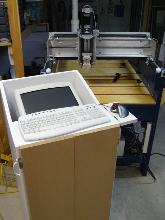
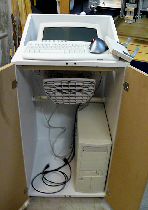
I started thinking about where the computer should go, especially the keyboard and monitor, and I finally saw this design for a computer cabinet on the Solsylva website, and liked it. In Fig. 28, you can see the side table for the trackball flips up out of the way when rolling it around, which is handy. The monitor is just resting on a couple of closet clothes rods. There is a wireless interface plugged in for net access, and next I'll put a surge protector in there so only the power and parallel port cables will go outside. Made from MDF, it rolls on casters and has lots of room. I think I need to make some kind of bevel around the monitor, though and maybe add a cabinet fan. I didn't paint the cabinet doors or add knobs yet, as I am starting to see any flat surface like that as a blank canvas in need of some serious carving. As soon as I get the table going, I'll carve up the doors and then paint them.
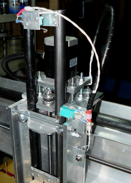
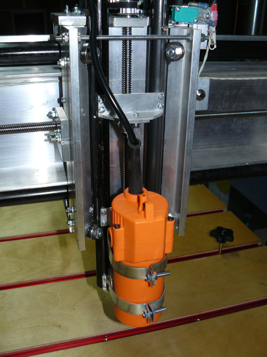
In Fig. 29 above I've finalized the wiring for the Z and Y axes, allowing for their movement up and down and across. Also, I've added a 1/4 inch jack (center bottom of picture) for a probe that will allow me to zero all three axes. This probe will have one electrical connection to the router bit, and another to the work. When the bit is positioned to the X, Y, and Z placement corresponding to the zero location, the machine will zero itself to that place. I've tried to keep the data (probe, temp, limit switches) separate from the power lines for the stepper motor, and trim router to prevent noise induction. Figure 30 shows the router mount as per the plans, but I am not real happy with it for two reasons - the bands to hold the router in place have to be custom made to fit the router, and the $20 HF trim router plastic case deforms when you apply too much squeezing like that. There exists some play in the router as a result. I think I will look into another router and figure out some kind of mount for it. Okay! Everything is wired up and ready to try. To get to this point took some head scratching, including formatting the computer's disk, reinstalling XP to SP3, and reinstalling everything else. Here is the first test run: Movie 1 Here is another video, showing an accuracy test I just completed: Movie 2 I just ran a similar test to the one above, except that when the gantry moves back, it traces out a 7x10 inch rectangle 100 times before returning. Same result - the zero position is within a thousandth. Makes for pretty boring video, though.
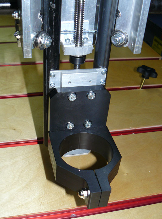
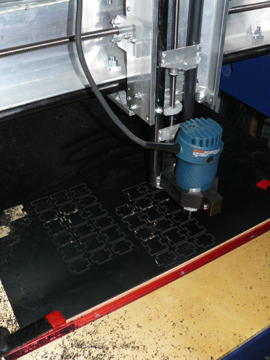
One of my net friends made the comment "Putting a HF router on your table is like putting a $5 spray can paint job on a Ferrari." I appreciate the complement, thanks! Rather than go through a trial and error process inventing a mount, I decided to just buy the one above for $49 from Probotix. It is made of delrin and sized to accommodate a 1 HP Bosch Colt trim router, which I found at Amazon for $71. The Colt is often used on these tables because they have very good runout, which means a bit in its collet spins very true with no wobble. {Note added later: This single speed Bosch router does not work with external speed controllers. Now, I wish I had gotten the variable speed version for $30 more.} To make the mount work, I replaced the two upright flat bars from the plans with a single 3/8 plate of aluminum, left over from the gantry sides, and drilled and tapped it to match the cross pieces of the carriage. I then drilled four holes to match the ones in the delrin router mount, and bolted it on with nylock nuts. Gives it a much sturdier base and a cleaner look as well. The carriage in the photo is lowered almost to its lowest limit so I could get behind it. Figure 32 shows my first cut! The Colt router is cutting the 1/8 inch plastic (with a 1/4 inch MDF sacrifice board under it) like its not even there. I used a straight flute 1/8 router bit and had no trouble with the swarf getting removed (thrown all over the room in fact.) These are the top and bottom pieces for some cable chain which is a design I got off the net by two fellows I've never met named Bertram and Shannon - Thanks, guys! Actually this is the power of CNC - getting a file off the internet that makes new parts for new things! The little plastic chips are flying everywhere, and are insidious to clean up. I need to make a vacuum attachment for the router mount. I also added some hinged walls all around the table that can be pulled down so that large boards may be placed through the table, but closed when smaller pieces are being cut, which is most of the time. This way, I only have to clean up the table top when done. These doors are shown on the first picture of the table on page one.
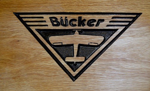
Ok, I said at the start of this log that I would update it until I could show some examples of the kinds of things you can do with this machine. Above are a couple of plaques it carved, starting from the scan of the logos (they are the logos of some antique aircraft) and then using Vcarve to generate the G Code which was then executed by Mach 3 telling my table what to do with the router bit. The carvings above are 1/4 inch deep. For another CNC project adventure click here. Or here. Or here. This completes the build log for the basic machine - the next page contains some add-ons and mods that were suggested after using the table for a while. |
||||||||