|
|
|
||||
|
Digital Read-Outs December, 2011. There really isn't any way to measure the depth of cut (Z axis, or quill depth) on this mill with much accuracy, and much has been written about the poor backlash and general accuracy of the X and Y table movement indicators on these mills. All this can be mitigated with a DRO system. DRO stands for Digital Read Out (which is a bit meaningless seeing how so many things nowadays, from my car to my microwave have "digital read outs." Even my refrigerator now has a DRO of the number of ounces of water dispensed into my glass!) but what it really means in this case is a relatively accurate display of the physical position along an axis of movement. Most DROs also have as part of their display, a microcomputer to help with offsets, trig functions, unit conversions, etc. but many have said they are functions seldom used. The main feature of a DRO is to be able to set the zero point at an arbitrary location on the axis, and then register accurate movement from that point in either direction, eliminating any backlash that may exist in the handle, screw, and leadnut. Since the advent of cheap calipers that are yet accurate to +/-.001 or +/-.002 inch, some have taken to just bolting them along an axis of table movement to use as a DRO, which works but has the problem of having the indicators at awkward places on the mill. Better accuracy can be obtained by using glass based sensors, but that is a big step up in cost and not needed in my case.
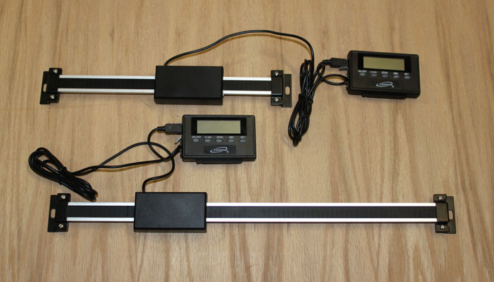
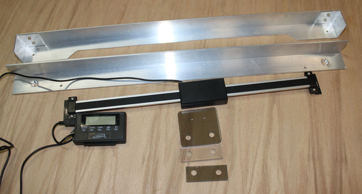
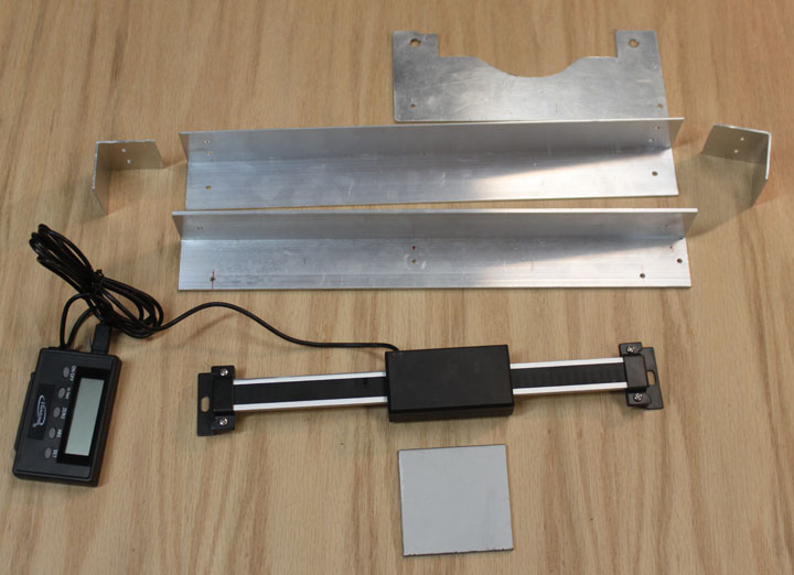
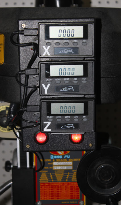
Fig. 1 The above units represent a nice compromise. The lower one, measuring 12 inches of movement, and the upper one, measuring 6 inches, will serve to indicate the movement of the X and Y axis respectively. The digital indicators are remote from the sensors, and will be located at a single location at eye level. Another 6 inch unit, not pictured, will be used for the Z axis. In addition, whatever scheme I use to mount these on the table will need to provide a cover for them to prevent swarf and cutting/cooling fluids from getting to the sensors. The only problem with these is that they need batteries, of which I am not very fond. The good news is that they cost (I got them from Taylor Tools on Ebay) $33 for the 6 inch and $37 for the 12 inch, so we are talking $103 for all three. A great website is Alan Pinkus's site which shows a method of mounting similar devices on the Z axis of an RF-25 type mill, which is the idea I'll follow.
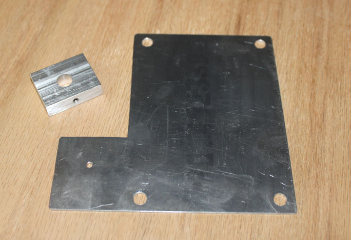
Fig. 2 Starting with the Z axis, the parts needed to mount the DRO are above. On the right, I made a plate that will fit behind the front cover plate of the mill with a tab on the left to hold the sliding sensor of the gauge. I used the cover plate as a template. On the left is a 3/8 thick piece drilled with a 3/8 hole on the flat surface, and a edge hole drilled and tapped 8-32. This is used to connect the DRO sensor to the drill stop arm.
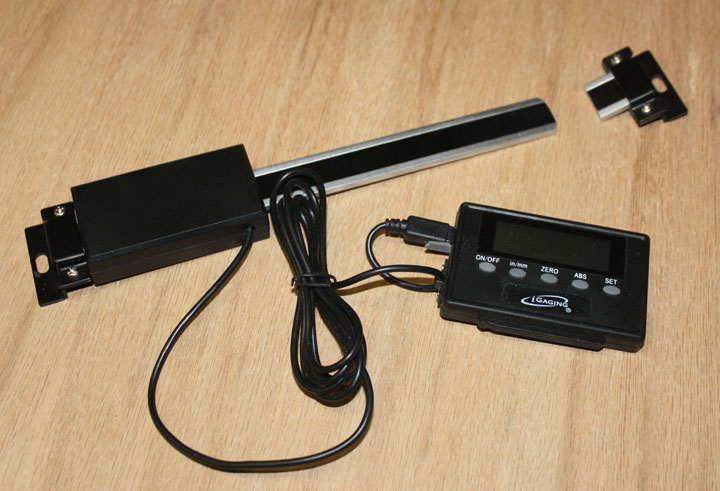
Fig. 3 The DRO (and digital calipers, for that matter) have three parts: the stator, which doesn't move and is the bar with the mounts on each end in Figure 1, and slider, which of course moves and is the black rectangle with the wire coming out of it, and the display at the other end of the wire. Briefly, these things work by using a passive printed circuit with a precise pattern glued onto the stator and then uses a sensor in the slider pick up the varying capacitance caused by the precise circuit board pattern as it moves. The result is scaled and presented on the display. Since the printed circuit on the stator is simply passive, it can be cut without affecting the operation of the device. The 6 inch stator is just a bit too long for this mounting, so I cut the hardened stainless steel stator with a angle grinder resulting in the two pieces shown above.
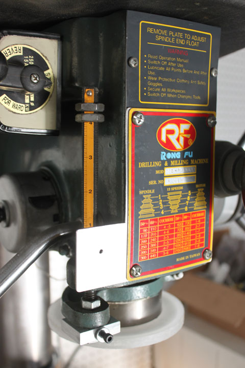
In Figure 4a you can see the pieces of Figure 2 mounted on the mill. The plate went under the front cover so that the speed chart of the pulley positions remain. The jam nut/threaded rod depth stop can still be set and used if needed. These two attach points allow the top of the stator to float, allowing some flexibility. In Figure 4b the DRO is mounted and ready to move. Note the wire that comes out of the slider on the right. This means that after you set a zero point, downward motion will show positive numbers, upward motion from zero will be negative. If you want it to work the other way, the stator needs to be cut off on the other end, and the wire will exit from the left of the slider.
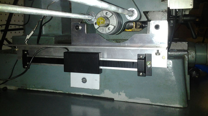
Fig. 5 Above are the parts I will be using for the X axis. These will go on the front of the machine, as I didn't want it to interfere with the rear movement of the table as the chip apron compresses against the column. It will mount in the slots which are for the stops, which will prevent their use. Since the DRO's accurately show position as well as the stops, this shouldn't be a problem but if it is, I can always use this same mount design on the rear by simply drilling and tapping two holes. The top angle bracket is .063, and just provides a cover for the front of the sensor to keep chips off the stator with some side panels I flush riveted on each end. The middle bracket attaches into the slot on the front of the table for the stops, and the stator will attach to it via countersunk bolts from behind. It is made of heavier .125 6061 since it will now be the front edge of the table. The stator will be mounted such that the wire of the sensor will emerges from the top, which means that positive X direction will be to the right, and negative direction is to the left. I cut an opening in the cover piece (on top in the Figure) to give more room for the wire. The top smoked Lexan piece attaches to the back of the sensor slide and the existing bolt holes on the table. The bottom two pieces are .25 and .125 thick Lexan needed as spacers.
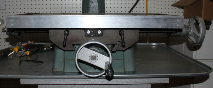
Fig. 6 Above shows the back of the X axis DRO installed. The left hand attach point of the stator is left to float, while the other end is tightened, both with Nylock nuts.
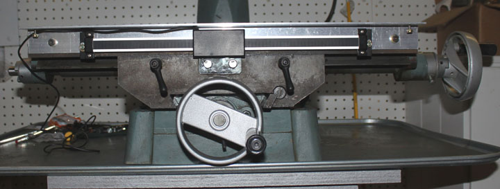
Fig. 7 Above shows the X axis DRO installed with the cover in place, ready to rock! However, the X table locking levers just under the DRO cover are a bit short to clear the cover.
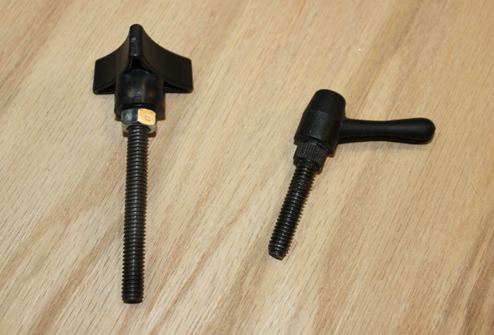
Fig. 8 Here I've made a substitute for the locking levers - a knob with a 5/16 insert and a jam nut and some 5/16 threaded rod to match, tightened with permanent threadlock. The extra length allows the knob to easily clear the cover. The original lock is on the right.
Fig. 9 Similarly, above shows the parts for mounting the Y axis. The main idea here is just like the X axis, except for the top plate that is used to attach to two new 1/4-20 holes drilled and tapped into the cast iron table. The white piece on the bottom is some Lexan to attach the slider to the table with its covering still on it to be drilled and fitted in place.
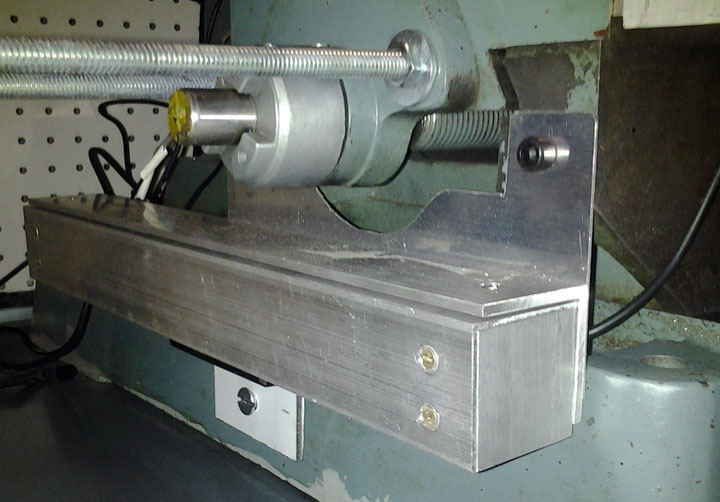
Fig. 10 Above shows the base of the Y axis DRO installed. A total of 3 holes were drilled and tapped into the table - two at the top of the stator cover bracket, and one in the base of the mill to hold the slide as the table moves in the Y direction. In the picture above, the threaded rods sticking out from the table are for the power feed mod described in another page.
Fig. 11 Above shows the base Y axis DRO installed with the cover on, which should keep chips off of the stator and slide.
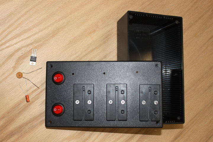
Fig. 12 Here are the parts needed for the DRO display. I decided to use the brackets that came with the DROs and mounted them on the cover of an $8 project box I had on hand. I thought about trying to mount them under the cover with cutouts to house the wires, but this seemed much simpler. I wanted a box to house a power supply for the DRO's and for the mill light described on another page. Right now, I will just use the 12 volt wall wart that powers the light to feed this box, but I have room to house a separate transformer, rectifier and filter if needed. The 12 volts will be sent to both $3 switches, one of which will send the 12 volts to the light, and one of which will feed the battery supply shown below. Both switches are lighted when on with a 12v LED so I don't forget and leave them on. The box is waaaay too large for what is needed here, but I already had it, and it does make a good panel for the displays. You can see I've also drilled holes for the wires to each display's battery compartment.
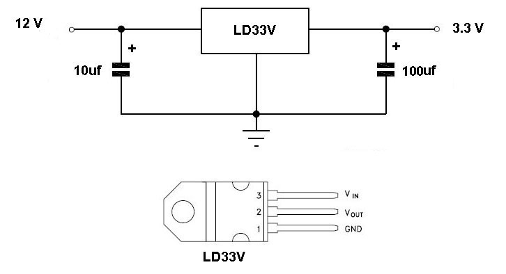
Fig. 13 Since the current draw by the display units is very slight, above is the circuit I am using to replace the batteries which uses a LD33V voltage regulator. Its output will go directly to the battery contacts in each display.
Fig. 14 Above shows the circuit shown in Figure 13 implemented as a stand alone assembly. On the left is the wiring with heatshrink on the individual wires, and on the right is the whole thing encapsulated in 1/2 inch heatshrink. Its output was measured at 3.29 volts. Since the current draw is so small, a heat sink won't be needed. NB: One thing I found later - the wall wart I was using was pretty crude and didn't regulate well - one of the units kept triggering off. The output capacitor value is from the data sheet of the LD33V. I changed it to a 100uF electrolytic and its now solid, and so I updated the schematic in Figure 13. You may or may not need to do this depending on the wall wart used.
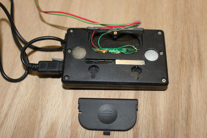
Fig. 15 Above shows how the power wires were connected to the display units. Since the battery contacts are so small, I soldered some 30 gauge wire-wrap wire (you could also just use a few strands of any stranded copper wire if need be) to the contacts as a pigtail to then be soldered and shrinkwrapped some larger gauge wire. The ground is connected on the right, and the plus side is connected on the left. You can also see the notch I cut in the battery cover to allow the wire to emerge.
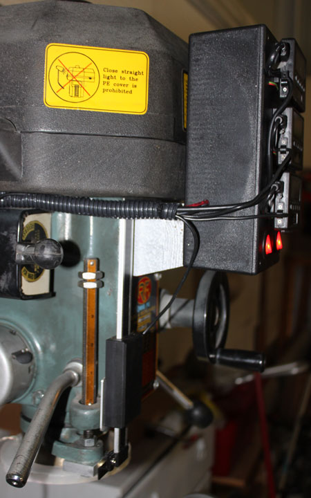
Fig. 16 Here the DRO display box is installed and everything up and running without batteries. Both switches are on and lit - the one on the left turns on the DROs and the one on the right turns on the LED ring light. Some simple white labels help avoid confusion. I thought a lot about where to place this box, thinking up articulated arms that would allow it to move out of the way of the quill levers on the right or the mill head crank on the left, etc. but the simplest was to place it right in front of the operator's eyes, so I made a wooden adapter painted with hammered silver that covers the upper part of the data plate, extending out so that the box clears the pulley cover and quill handcrank. By the time the cables are routed out of the way with enough slack to facilitate full table movement, there is way too much cable for the Z axis remote, enough for the Y axis, but not quite enough for the X axis cable to go around the back of the mill. I ordered a 3 ft USB extension cord from Amazon for $9. That's why the wire to the X display in the above figure is a bit thicker than the other two. These, plus the power cord to the display box were tucked into some split cable loom and attached to the mill.
Fig. 17 Here is the display box from the side, showing the silver wooden spacer and split cable loom. Overall, I am very pleased with these - they are giant leap above dealing with the ridiculous backlash on the table crank dials. The only big drawback is normally a good feature for battery powered units - auto shutoff. (If my digital calipers didn't auto shutoff after a few minutes idle, they would all be battery dead!) After eliminating the batteries on these units, the auto shut off feature (happens after about 5 minutes) is not wanted. However, when one shuts off you only have to press the power button again, and your setting is still preserved, so its not that big a deal, IMHO, as long as you remember to press the power button and not one of the others. The repeatability on these is excellent - zeros back to the nearest .001 (as good as I can measure.). Its accuracy though, is only supposed to be good to the nearest .002 over 6 inches. Most of the stuff I do involves offsets less than 3 inches, which would keep it good to the nearest .001. Nota Bene from the future: The cost of proper glass scale DROs have come down so much since I added these that they are about the same price, and I would no longer use this kind of DRO. There is a movie link at the bottom of the power feed page showing the DRO's working. |
|||||