|
|
|
|
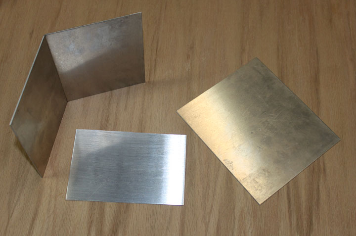
January, 2012 Normally, a power feed is most useful when you have a lot of milling to do and you don't want to have your arm look like Popeye's after a days work. Since I don't plan on doing much production work, I didn't think this would be all that necessary, but just like on a lathe, a power feed can help produce a nicer, more consistent finish on milled surfaces. As long as the cost was low in both time and money, it might be a good thing. I've seen several schemes employed on the net using windshield wiper motors and battery powered hand drills. I came across a post by Rick Grimm (thanks Rick) on the grizzly mini mill yahoo group about a drive he built for his Grizzly mini-mill. It won't connect to the X-Y table like mine will, so I will have to come up with a different mount and adapter for the drive shaft, but the motor he used is interesting. It is a 144 RPM gear drive DC motor for only $18 that runs on 24 volts. I also got a power supply meant for a printer that puts out 3 amps of 24 volts. ($12 including shipping) and a PWM motor controller for ($10 incl shipping). I got a DPDT On-Off-On switch to reverse polarity to the motor, which reverses its direction. I also got a numbered knob for the controller from a local electronics store, as well as a 2.1 mm jack for the power supply.
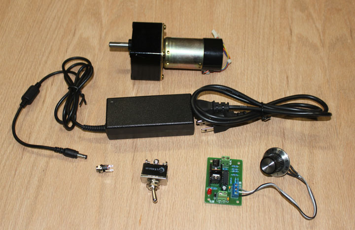
Fig. 1 Figure 1 shows the parts just described, total of $44 in damages. That drive motor actually has an encoder on the back of it, but I probably won't need to use that. Now all I need is a way to mount the motor, and make an adapter to mate the drive shaft with the attach point where the hand crank is now.
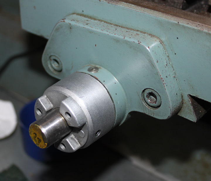
Fig. 2 The picture above shows how the crank handle attaches to the threaded rod that moves the X axis - there are three "prongs" that mate with identical ones on the handle. A set screw is all that is needed to keep the handle on. I could remove all this and make a new bearing housing for the rod, but I would like to make as few changes to the mill as possible. So, I need to make piece that mates the above attach point to the motor shaft, which is simply a .3 rod with a flat on it it.
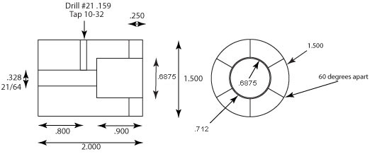
Fig. 3 The next step was to draw up the sliding coupler part dimensions. I think leaving the coupler exposed and just sliding it by hand will be enough, even though a lever to move the coupler could be arranged. I think once it is working, moving the table by handwheel will not be needed very often.
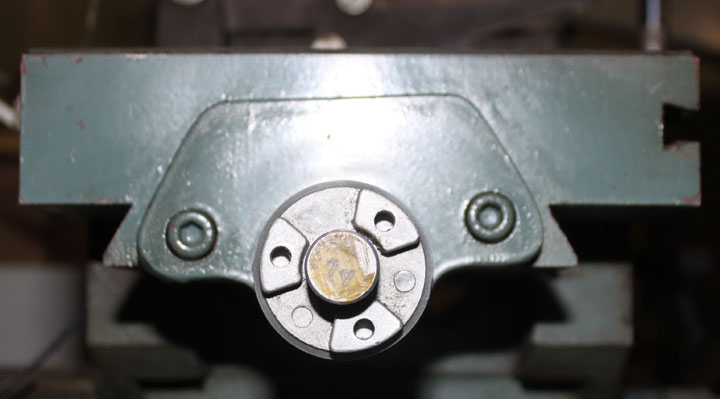
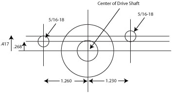
Fig. 4 One issue is dealing with the erratic machining that was done when the mill was manufactured. The above is a picture of the left hand bearing housing taken from the side and is a case in point. Notice how the 5/16 hex head bolt holes that attach the bearing housing are not parallel to the top of the table? The hex bolt hole on the left was drilled about 0.15 inches too low and they are slightly off from being the same distance from the drive shaft center. The bolt holes on the mill's right hand housing are more parallel, but I want to keep the hand crank on that side since I am right handed. I'll just have to make the measurements as best I can and make sure the rod placement matches. One thing you can say about these mills - "No two are the same!" Here's how I came up with the measurements: By importing the above photo into a tracing program, then blowing up the image until the measured diameters of the shaft and handle ring match those in the photo, I was then able to fairly accurately measure the hex bolt hole centers to come up with the following engineering drawing:
Fig. 5 From this I can figure out how the drive box needs to be mounted.
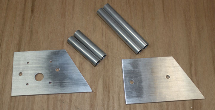
Fig. 6 Here are the main parts for the motor mount frame, plus some 5/16 threaded rod not shown. The 3/8 thick plate I had on hand. The tubing is 6061 with .125 inch wall and a .5 inch ID which I got from McMaster Carr ( item 9056K712 for 3 feet of it at $21 - but 2 feet of it would have been more than enough.) I decided to angle the front to accommodate the controls - there should be plenty of room on the bottom for the motor controller, and a power jack on the back.
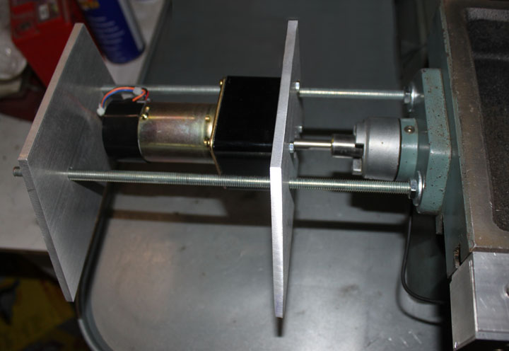
Fig. 7 Here you can see what I have in mind. The motor output shaft is concentric with the table leadscrew shaft. Also, the threaded rods line up with the holes in the plates perfectly and the tops of the plates are even with the surface of the table, minus a bit for the cover. (Note that when I went to take this picture, the plate on the left was slipped on backwards - it is correctly oriented in Figure 8.) Although the motor will just be cantilevered out there, this is the simplest approach. The tubing spacers will be added to the rods to provide a bit more secure support, shown below. Perspective and lens distortion makes it look like the rods are bent, but they are actually straight.
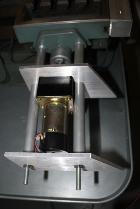
Fig. 8 Here is the frame in place. All that is needed now is the slip coupler, the drive controller, and some skin around it. I will trim off the excess threaded rod length after everything is properly fit.
Fig. 9 Above shows the parts to the skin - since the top front edge is open to hand movement, I decided to make that a bend rather than a cut edge, so it matches the 120 degree angle of the side plates. The right piece is the bottom, and the smaller piece is the back. I decided to go with .064 6061 to give it some strength.
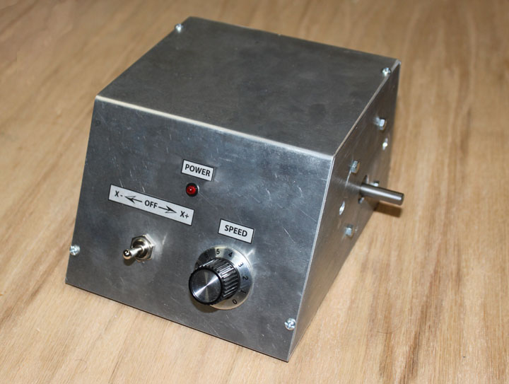
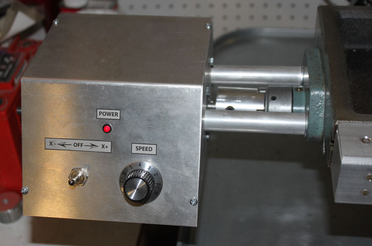
Fig. 10 Here is the assembled box with the front panel parts mounted. I drilled and tapped 6-32 holes to keep the cover in place, as well as the back plate, drilled to mount the power jack, and the bottom plate. I decided to include an LED (along with a 1.2 kohm resistor to make it compatible with 24 volts) to indicate when the power was on. The switch on the left is ON-OFF-ON so that in the center position the drive motor is not turning. On the left position, the motor is turning counter clock wise (table moves to the left) and when the switch is to the right, the motor turns clockwise and the table is on the right. Coupled with the DROs, this means the left position decreases the value of X axis, and the right position increases the value of the X axis position. The unit works pretty well - the motor has plenty of torque. The labels are just laser printer clear labels done with a drawing program. Perhaps I should put a "No Step" decal on the top of the unit to remind me not to set anything on top of it!
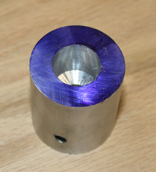
Fig. 11 Above is the coupler (whose design is in Figure 3) after a few operations - I took a length of 1.5 inch round 6061 stock, chucked in a mini lathe and made a light pass over its length and faced each end. I then drilled a longitudinal hole slightly larger than the diameter of the motor shaft all the way through and widened it to .725 about halfway down. In the middle of the thicker section I drilled and tapped a 1/4-20 radial hole for a set screw. I then used some Dykem (a "permanent" marker will work just as well) on the end ridge to color and mark the position of the "ears" that are to be milled 120 degrees apart.
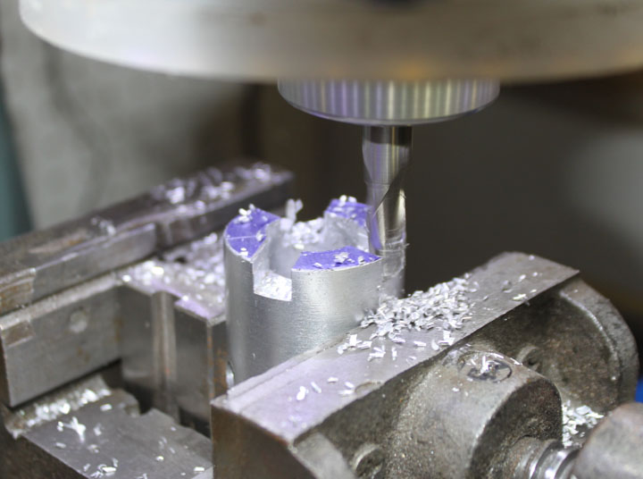
Fig. 12 Above is the end of the coupler being milled in the mill to mate with the handle "ears" of the mill. It used a 3/8 end mill, making three separate cuts in three passes each.
Fig. 13 Here is the completed power drive plugged in and ready to move. The set screw was set to provide as little as backlash as possible while still allowing it to slide, and locked in place with some thread locker. The coupler slides left and right on the motor shaft to engage/disengage the drive, and the table moves smoothly back and forth at varible speed. Below is a short movie of the DROs and the power feed working. There is no music or narritive added so that you can hear the drive working. |
|